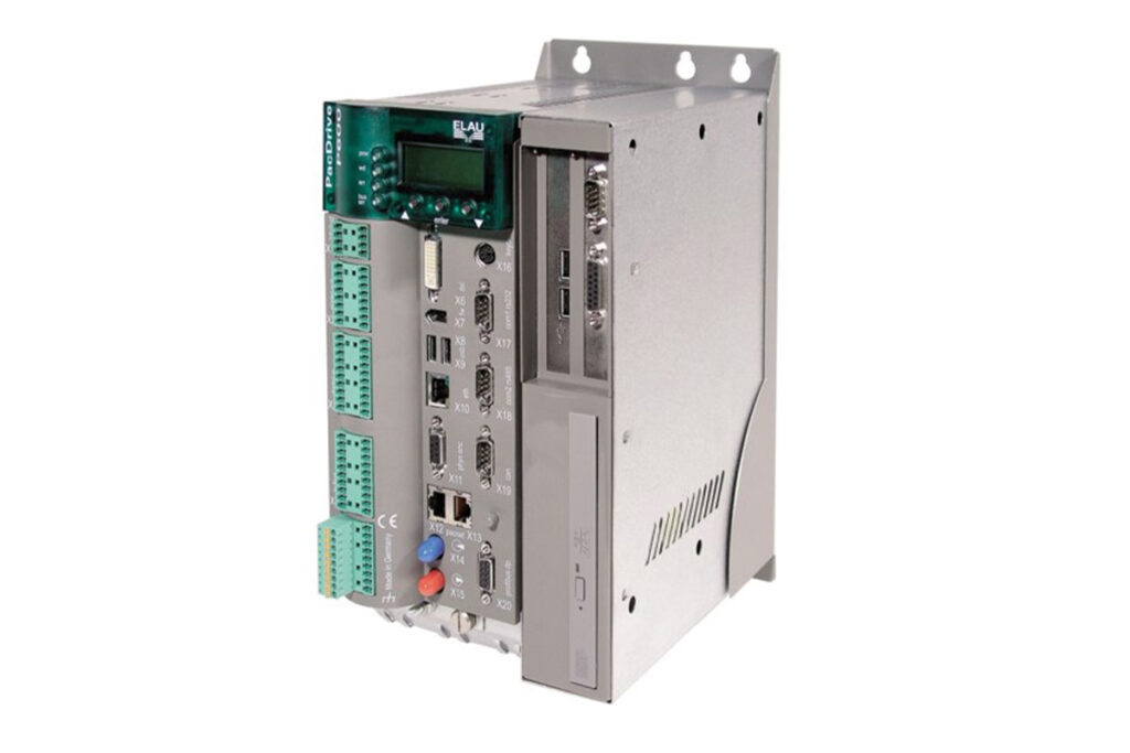
ELAU PacDrive Controller P600
ELAU PacDrive Controller P600
The PacDrive Controller P600 is equipped with the VxWorks real-time system and the Windows XP operating system. Take into account both systems when switching the controller on/off or resetting the controller. The PacDrive controller P600 works with three network addresses. For the two integrated systems (real-time system VxWorks and the Windows XP operating system) the distribution is designed as follows.
| Order number | Item name: | Explanations |
| 13 13 02 63 | PacDrive P600 / 10 / 1 / 1 / 1 / 1 / 1 / 00 | P600 |
| Parameters | Value | |
| Product configuration | Type code – P600 up to 22 SERCOS nodes (SERCOS nodes MC-4, SCL, iSH) | PacDrive P600 / 10 / 1 / 1 / 1 / 1 / 00 |
| Order number – P600 up to 22 SERCOS nodes | 13 13 02 63 – 001 | |
| Processor | CPU | Intel Pentium M 1.6 GHz |
| RAM | 512 MB | |
| L2 Cache | 1 MB | |
| NVRAM | 256 kB | |
| CompactFlashTM card (X21) | not required | |
| Real time clock (RTC) | yes (battery maintenance interval: 5 years) | |
| Watchdog | yes (max. 60 V < 2 A) | |
| Diagnosis | alphanumeric diagnostic display, Status LEDs | |
| PC configuration | HDD | 40 GB |
| DVD-ROM | 8 x DVD / 24 x CD-ROM | |
| PS2 (X16) | Number: 1 | |
| USB 2.0 (X8 / X9) | Number: 2 | |
| IEEE1394 (FireWire) (X7) | Number: 1 | |
| DVI (VGA) (X6) | Number: 1 | |
| PCI slots | Number: 2 | |
| Operating system | Real-time operating system Applications operating system | VxWorks RT Windows XP |
| Programming languages | Programming language IEC 61131-3 (CFC can also be used) | Instruction list (IL) Ladder diagram (LD) Function block diagram (FBD) Sequential function chart (SFC) Structured text (ST) Continuous function chart (CFC) |
| Interfaces | serial interfaces COM1 COM2 | RS232 (X17) RS485 (X18) |
| Network connection | Ethernet (10/100 Base-T) (X10) | |
| Field bus connection | PROFIBUS DP Master/Slave (12 MBaud) (X20) or CAN (2.0A) or CANopen (X19) DeviceNet Slave 2) Ethernet/IP Adapter 1) EtherNet/IP Scanner1) (projected) 1) optional hardware module required 2) cable adapter required |
| Parameters | Value | |
| Real-time bus interface | SERCOS interface (16 MBaud) (X14, X15) | |
| PacNet interface | 2 PacNet interfaces (X12, X13) | |
| Master encoder interface | 1 SinCos master encoder or 1 incremental master encoder (X11) | |
| HMI interface | User display devices: RS485 (Modbus or PROFIBUS DP) HMI software tools: OPC server for PacDrive controller P600 (Windows XP) or for an additional PC (Windows NT/2000/XP or Windows CE) | |
| Diagnostic interface for remote maintenance | Web server or modem | |
| Communication protocols | http, ftp, SMTP (email) | |
| integrated trace recorder (soft‐ ware oscilloscope) | 8 channels resolution 1 ms | |
| integrated data logger for diag‐ nostic messages | 27 kB | |
| Output | Actuator power | 8 servo axes: SERCOS cycle time 1 ms 14 servo axes: SERCOS cycle time 2 ms 22 servo axes: SERCOS cycle time 4 ms max. of 255 parallel motion profiles possible |
| PLC output | Time for 1000 Bit instructions: 4 µs unlimited number of PLC processes Type of PLC processes: continuous, periodic or event-driven Cycle time fast task: 250 µs nominal I/O response time: 500 µs (read in data, process, set output) | |
| Cam switch group | Cam switch group | max. 256 cams dynamic switch group Outputs: Memory or digital outputs Inputs: external master encoder, virtual master encoder, axis position Processing time: 250 µs |
| I/Os | digital inputs (X3) | Number: 20 (IEC61131-2) Range UIN 0 Voltage: DC 0 … 6 V Range UIN 1 Voltage: DC 20 … 33 V input current: IIN = 5 mA at UIN = 24 V polarized yes input filter: 1 or 5 ms can be parameterized |
| analog inputs (X2) | Number: 2 Range UIN: -10 … 10 V; Resolution 12 Bit, 5 mV (Resistance 100 kOhm) or Range IIN: 0 … 20 mA; Resolution 12 Bit, 5 µA (Resistance 500 Ohm) | |
| Interrupt inputs (X4) | Number: 4 (IEC61131-2) Range UIN 0 Voltage: DC 0 … 6 V Range UIN 1 Voltage: DC 20 … 33 V input current: IIN = 5 mA at UIN = 24 V polarized yes input filter: 0.1 or 1 ms can be parameterized |
| Parameters | Value | |
| Touchprobe inputs (X4) | Number: 16 (IEC61131-2) Range UIN 0 Voltage: DC 0 … 6 V Range UIN 1 Voltage: DC 20 … 33 V input current: IIN = 5 mA at UIN = 24 V polarized yes input filter TP0 to TP15: 100 µs resolution TP0 to TP15: 10 µs at a cycle time of 1, 2, 4 ms | |
| digital outputs (X2) | Number: 16 (IEC61131-2) Output voltage: (+UL-3 V) < UOUT < +UL Rated current: I e = 250 mA per output Inrush current I emax < 2 A for 1 s Leakage current 0 signal: < 0.4 mA Transmission time: 100 µs Short-circuit proof: yes Supply outlet: DC 24 V (-15% / +25%) / 3 A | |
| digital outputs (X5) | Number: 2 Range UOUT: -10 … 10 V; Resolution 12 Bit (5 mV); Load > 5 kOhm (max. offset < +/-75 mV) | |
| additional digital and analog I/Os | via field bus max. 3,584 bytes digital/analog inputs and max. 3,584 bytes digital/analog outputs max. number of stations: 126 (PROFIBUS) | |
| additional fast digital I/OS | via PacNet max. 128 inputs and 128 outputs | |
| additional Touchprobe inputs | via PacNet max. 128 Touchprobe inputs | |
| Power supply | Power supply unit | DC 24 V (-15% / +25%) / max. 3.0 A without UPS and 4.5 A with UPS |
| Power consumption | max. 85 W | |
| Uninterruptible power su pply (UPS) | internal, optional (maintenance interval 3 years) | |
| Dimensions and ambient conditions | Dimensions Dimensions packaging | see chapter Dimensions Width: 180 mm Height: 400 mm depth: 300 mm |
| Weight Weight with packaging | 5.6 kg 6.2 kg | |
| Ambient conditions – Protection class – Ambient temperature – Insulation class – relative humidity | IP 20 +5…+55 °C (Operating temperature without UPS) +5…+40 °C (Operating temperature with UPS) -25…+70 °C (Storage and transport without UPS) -25…+50 °C (Storage and transport with UPS) Degree of pollu‐ tion 2 …, no thawing 5% … 85% climatic category 3K3 EN 60 721 | |
| Approval | Approval | CE, UL , cUL |