ELAU PacDrive M EPAS-4
ELAU PacDrive M EPAS-4
For you as a user, this means:
- Quick familiarisation, easy handling, all tools integrated.
- ELAU maintains extensive libraries geared to the packaging industry, helping you obtain cost effective and speedy answers. They can also help you to improve the quality of your user programs.
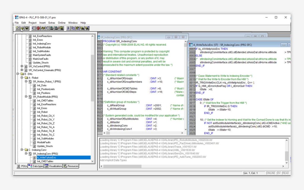
- Runs under Windows (as of Win95)
- Programming language IEC 61131-3
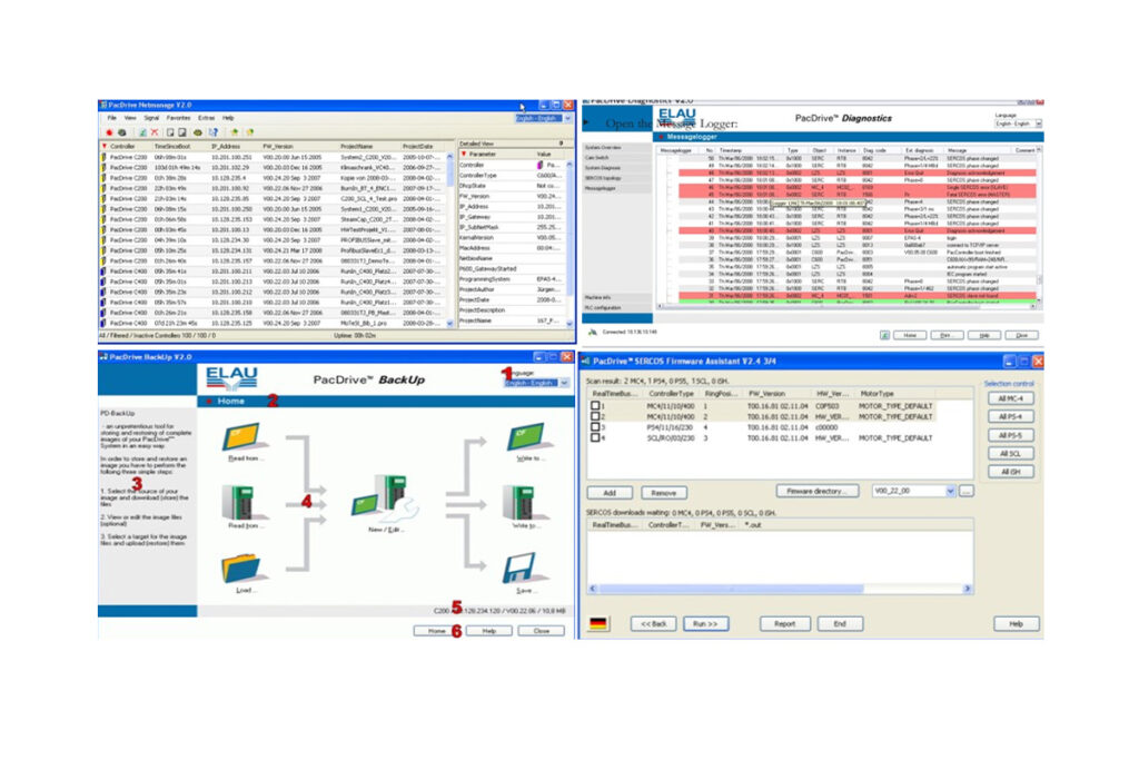
- SCOPE tool (oscilloscope functions)
- Diagnosing tool
- Very good debugging features
- Serial or TCP/IP connection to the Max-4 PacController
Around the end of the 1980s, a development started that made Programmable Logic Controls (PLCs) central components of automation technology. The PLC systems have various advantages compared with conventional relay technology, for example, they can be adjusted quickly in case of process changes and are easily extendable. The function and structure of the systems are independent of the size of the PLC. A PLC consists of hardware and software, with the hardware comprising a processor with storage components and further electronics for the connection of input and output systems. Modular PLC systems consist of various components such as component carriers with system bus, power unit, central processing unit and application storage, digital inputs and outputs and intelligent components for analogue data processing or drive control. For the input and output level, a standardised voltage of 24 V has been set leading to a resistance complying with industry requirements.
The software comprises the operating system and the application program. The operating system manages the system resources and the organisational functions and in addition, ensures a controlled start after the operating voltage is switched on. It is responsible for error management, enabling the exchange of information via communication groups and also coordinates the execution of the application program which maps the logic course of the control task.
A PLC starts processing the application program immediately after it is switched on (in the so-called RUN mode). Directly after the system is switched on, all non-remanent memories are reset and the processing cycle starts scanning in the input image after which the complete PLC instruction list is processed. In the next step, the output image created through the instruction list is sent to the outputs and the program cycle starts again with scanning in the input image. The cycle time is probably the most important speed criterion for a PLC, typically ranging from some ms to several hundred ms.
The simple flow structure shows its advantages when data and programs are manipulated in ongoing operation. Almost all programming environments allow for the change of all variables during a processing cycle. Due to the set program structure, program sequences can be loaded at run time (Online Change), since there are always exact starting points at the beginning and the end of a cycle. When these new systems were launched, the producers had to make their customers, who were used to contactors, acquainted with the programming of the new systems. For that reason, numerous but mostly short-lived attempts were made to find a programming language that facilitated the change from the traditional detailed wiring diagram to the PLC program. The programming languages, Function Block Diagram, Ladder Diagram and Instruction List, were then developed. At that time, however, developers failed to define a universally binding standard for programming PLC systems. As a consequence, each producer had specific characteristics in the programming languages Function Block Diagram, Ladder Diagram and Instruction List. Therefore, company standards emerged in various geographic regions, such as Siemens STEP 5 in Europe, Allen Bradley in the U.S. and MITSUBISHI in the Far East.
In recent years, the complexity of the applications and thus the programming costs has grown over-proportionally. The producers’ specific standards did not ensure the programs could be reused and due to these reasons, the IEC standard IEC 61131 was developed at the beginning of the 1990s under the lead of the International Electrotechnical Commission (IEC). Within the context of this process, the new languages Structured Text (ST) and Sequential Function Chart (SFC) were defined in addition to the existing languages Ladder Diagram (LD), Function Block Diagram (FBD) and Instruction List (IL). IEC 61131 sums up the requirements for a modern PLC system. The standard was not intended as a rigid specification, but as a guideline for PLC programming. Accordingly, the standard describes the significant properties of an PLC while leaving manufacturers enough room to use their own implementation. IEC-61131 tried to bring modern software engineering into the PLC world, which was necessary due to more complex processes and functions and the cost explosion of development of application programs. Tested and standardised software modules which can be re-used was regarded as a solution, however, this is made more complicated due to:
- direct addressing
- untypified variables,
- no type check.
In general, the objectives of IEC 61131 are:
- application of software engineering methods with the aim of reusable software modules
- holistic approach to problem solutions
- abstraction of complex tasks into smaller modules
- definition of unambiguous interfaces
- standardisation of the language scope in order to increase portability.
In addition to the elements for the programming and organisation of the application program, IEC 61131 also gives guidelines for modelling and structuring PLC composite systems. To structure the system, the concepts of configuration and resource were introduced. The model also takes into consideration properties such as multiprocessor systems, modern PLC operating systems featuring multitasking properties, unlimited number of analogue and digital inputs and outputs and the ability to communicate with other PLCs and computers. A configuration defines the structure of a system, for example, this can be a PLC with several, even networked, CPUs on machine cell level. A configuration is comprised of one or more resources which represent sub-controls with its own signal processing functions. In a real configuration, a resource is represented by a PLC CPU, which in most cases has multi-tasking capabilities. A resource is structured with the help of one or more programs which are controlled via tasks. A task is an executable program unit to which both a priority and an execution type are assigned. Therefore, execution lines with different properties can be formulated within one and the same program. Thus, not only cyclic tasks with a system-wide uniform cycle time are possible. Cycle times can also be combined and event-controlled program units can be made available in the system. By assigning a certain priority to a task, CPU time is allocated to a resource.
The run time properties of the complete program, which can run independently in a CPU, are defined by linking programs to a certain task. Thanks to the flexibility of the system modulation, a program can be linked to several tasks, thus creating several instances with different run time properties. IEC 61131-3 supports local data that can be declared in programs, function blocks or functions. Local data can only be accessed in the corresponding program hierarchy level and represent a mechanism for data encapsulation. Of course also resource-wide available global data available for all program elements are possible. If multitasking systems are used, however, access to global data is a risk source for inconsistent data. In addition, there are directly accessible data with fixed addresses within the PLC address range.
An essential aspect in the description of the structural elements is the data exchange. With the help of the communication model defined in the IEC 61131, it is possible to create well structured and in particular modularised PLC programs, which is a fundamental basic characteristic for the development of application-oriented, reusable program modules. In priniciple, IEC 61131 provides for the following communication possibilities:
- access paths (VAR_ACCESS)
- global variables (VAR_GLOBAL, VAR_EXTERNAL)
- call parameters
- communication modules (IEC 61131-5)
All elements of a configuration communicate with each other and also with other computer systems exclusively via defined access paths. In addition, global variables are used for the simple communication of programs within a configuration. Global variables can be placed and used on configuration, resource and program level. The data exchange within programs is effected via call parameters, input and output variables or function values. Although high-level language programmers are familiar with this structural tool, it brought fundamentally new aspects into conventional PLC programming. Call parameters and transfer variables allow for the definition of unambiguous interfaces and thus make an important contribution to the encapsulation of functionality. In addition to the elements of the communication model described so far, also special “communication modules” can be used. They are of monolithic nature and are linked into a program. Thanks to those modules, data exchange between sender and receiver is self-sufficient. Communication services are defined in part 5 of IEC 1131, which is still being edited, however, looking at the communication model of IEC 1131, the good support of standardised software modules is particularly striking. Thanks to the encapsulation of functionality and data, a clearly defined interface and a side-effect free behaviour, the acceptance of the modules among users has increased significantly. An important standardisation of programming languages according to IEC 61131-3 is the definition of data types. The norm includes various elementary data types from which derived and user-defined data types can be composed. The user can use standard data types and self-defined data types for programming. Assigned to each identifier is a data type that defines how much memory space is reserved and which values correspond to the memory content.
Contact Us for Schneider Electric PacDrive Support:
Repair. Replace. Train. Maintain. Your ONE STOP SHOP for your ELAU PacDrive needs. Now and in the future.